Baluns, Chokes, and the Common-Mode Current Nobody Warned You About
Half of the mysterious antenna problems in amateur radio are one problem wearing different masks. Here is what common-mode current is and how to stop it.
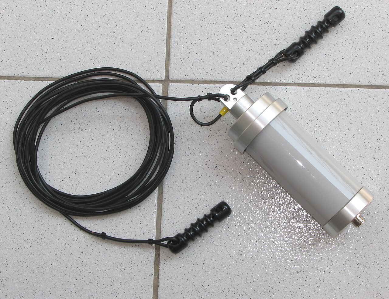
The third conductor you did not design
Coaxial cable looks like it has two conductors: a center wire and a shield. At radio frequencies it effectively has three. Current flows on the center conductor, current flows on the inside surface of the shield, and a third, independent current can flow on the outside surface of the shield. That outer-surface current is called common-mode current, and it is the single most under-diagnosed problem in amateur radio.
The first two currents are equal and opposite, so their fields cancel and the cable neither radiates nor receives. The third current has no partner. It turns your feedline into an antenna, which means the feedline radiates part of your transmitted power in whatever direction it happens to run, and it means the feedline picks up every noisy switching supply and LED bulb along its path and delivers that noise straight into your receiver. Almost everything operators describe as a haunted station traces back to this one mechanism.
The symptoms, so you can recognize them
Common-mode current announces itself in a consistent set of ways. The SWR reading changes when you touch the radio or the coax. RF gets into your microphone audio and other stations report a buzz or a hum on your signal only when you use one particular antenna. Your computer, monitor, or keyboard misbehaves when you transmit at full power. The receive noise floor rises sharply when the coax is routed along a particular wall and falls when you move it. Nearby consumer electronics react to your transmissions even though the antenna is far away. Any two of those symptoms appearing together is enough to justify installing a choke before you change anything else.
Balanced, unbalanced, and why the mismatch matters
A dipole is a balanced load: two symmetric halves, equal and opposite currents, no preferred reference to ground. Coaxial cable is an unbalanced feedline: the shield is nominally at ground potential and the center conductor swings against it. Connecting an unbalanced line directly to a balanced load is the textbook recipe for common-mode current, because the antenna has no reason to keep the two shield currents symmetric. Some of the return current, finding the outside of the shield an easier path than the antenna leg it was supposed to take, simply goes there instead.
This is not a small effect. On a poorly matched installation, a substantial fraction of your power can end up on the feedline rather than the antenna. The pattern distorts, the null directions fill in, and your feedline becomes the dominant receive antenna, complete with all the household noise it runs past.
What a balun actually does
The word balun is a contraction of balanced-to-unbalanced, and that is exactly the job: it lets an unbalanced line feed a balanced load without the asymmetry leaking onto the outside of the shield. There are two distinct mechanisms sold under the same name, and confusing them is the source of endless bad advice.
A voltage balun forces equal and opposite voltages at its two output terminals. A current balun, also called a choke balun, forces equal and opposite currents by presenting a high impedance to any common-mode path. For antenna feedpoints, the current balun is almost always the right answer, because what you want to suppress is a current, and the antenna itself will sort out the voltages. Voltage baluns have legitimate uses in matching networks and tuners, but a voltage balun at a dipole feedpoint on a real installation often underperforms a simple choke.
Building a choke that actually works
The cheapest effective common-mode choke is coax wound through or around ferrite. For HF work, a stack of type 31 ferrite cores with the coax passed through them several times, or a coil of coax wound on a type 31 toroid, produces several thousand ohms of common-mode impedance across a wide range of bands. The old trick of coiling ten turns of coax into a loop and taping it also works, but only over a narrow frequency range, because it is a resonant solution rather than a lossy one. Ferrite is broadband and forgiving; air-wound coils are cheap and fussy.
Choose material by frequency. Type 31 is the standard choice from 1 to 30 MHz. Type 43 is better above 30 MHz and works for VHF and UHF. Getting this wrong is one of the few ways to install a choke and see no improvement at all. Commercial units from reputable makers cost about the price of a decent coax connector kit, come with real impedance curves, and are worth buying if you dislike winding toroids.
Where to install them
Two locations do most of the work. The first is at the antenna feedpoint, which is where the imbalance originates and where suppression is most effective. The second is at the point where the coax enters the building, which stops whatever common-mode current is still riding along the line from being delivered into your shack and coupling into everything else.
For an end-fed half-wave, install the choke on the coax side of the transformer, not between the transformer and the wire. For a vertical with radials, a choke at the feedpoint still helps, because a radial field is never perfectly symmetric. For a beam on a tower, chokes at the feedpoint and at the bottom of the tower will quiet a station noticeably. None of this replaces good grounding and bonding, which is a separate and equally important subject.
The diagnostic that settles arguments
Clip a current probe or an RF current meter around the outside of the coax a few feet from the radio and transmit at low power. A well-choked feedline will read close to nothing. A feedline carrying significant common-mode current will read a number that makes the problem undeniable. Install the choke, measure again, and you have a before-and-after comparison instead of an opinion.
If you do not own a current probe, the poor-man's version is to watch your SWR meter while a helper runs a hand along the coax. If the reading moves, current is flowing where it should not. That test takes thirty seconds and has saved more antenna projects than any amount of theory.
Every HAMSTATION tool runs entirely client-side. No accounts, no tracking, no server storage.
Open the toolkit →