Installing Coax Connectors: PL-259 Soldering and Better Alternatives
The connector you built yourself is the most likely failure point in your station. Here is how to make one that lasts twenty years outdoors.
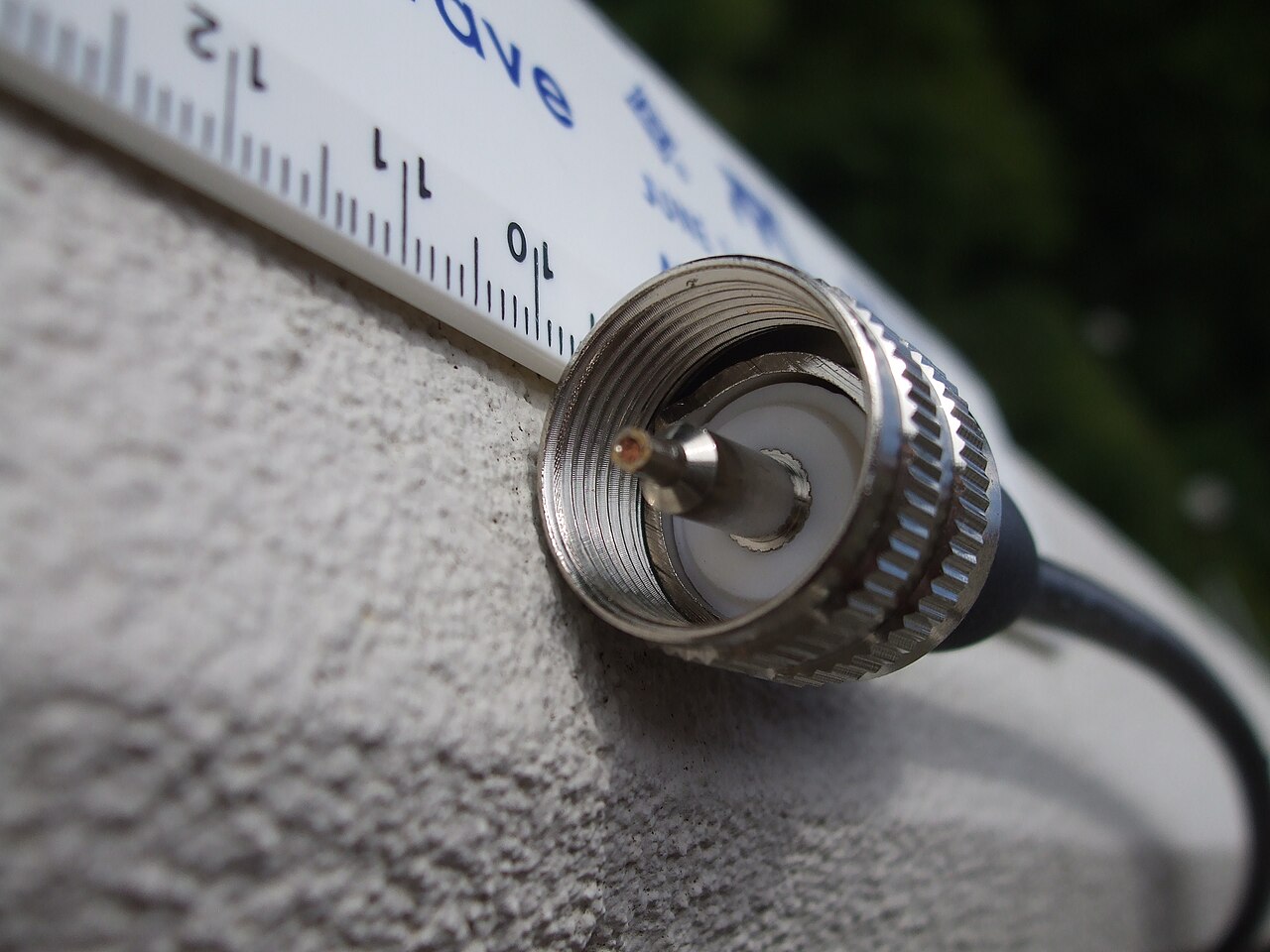
The failure point you built yourself
Ask any experienced operator to name the most common cause of a station that mysteriously degraded over a season and the answer will be a connector. Not the radio, not the antenna, not propagation. A connector, usually one that somebody assembled in a hurry, usually the one at the top of the mast where the weather is worst and access is hardest. Water wicks into a poorly sealed joint, corrosion builds between the braid and the shell, and over a few months the station quietly loses several decibels in both directions.
This is entirely preventable, and it is one of the few areas of amateur radio where twenty minutes of careful work produces a result that lasts two decades. The techniques are old, well documented, and unglamorous, which is precisely why they are worth writing down.
Why UHF connectors are everywhere
The connector amateurs call a PL-259, and its socket the SO-239, belongs to a family designated UHF, which is a historical misnomer of the highest order. The design dates to the 1930s, it is not constant-impedance, and its performance degrades above roughly 300 MHz. It became the amateur standard because it is cheap, mechanically robust, tolerant of clumsy assembly, and available everywhere.
For HF work through the 6 meter band, the impedance discontinuity is negligible and there is no practical reason to use anything else. Above that, and particularly at 70 centimeters and higher, the connector's loss and mismatch become measurable and the correct choice is a type N or, for small cable, a good SMA. Using a UHF connector at 1296 MHz is a genuine mistake; using one at 14 MHz is completely fine and anyone who tells you otherwise is selling something.
Soldering a PL-259 properly
The classic assembly uses a reducing adapter for smaller cable such as RG-58 or RG-8X, or direct entry for full-size RG-213. Strip the jacket to expose the braid, fold the braid back over the jacket, thread the adapter on, then trim the dielectric and center conductor to the correct depth so the center pin seats fully without bottoming out.
Two soldering steps matter and both are done wrong constantly. The center pin must be filled with solder and the conductor fully wetted, with no excess mushrooming past the tip, because a proud blob prevents the connector from seating in the socket. The four side holes in the shell must be soldered to the braid, and this is where people fail: they either use an iron too small to heat the brass shell, producing cold joints that look fine and conduct badly, or they use a torch and melt the dielectric, changing the impedance and eventually shorting the connector.
Use a large soldering iron, at least a hundred watts or a heavy gun, get in and out quickly, and let the assembly cool before moving it. Then test continuity from center pin to center conductor, from shell to braid, and between center and shell, which must read open. A connector that fails that thirty-second test on the bench will fail on the tower in a rainstorm instead.
Crimp and compression alternatives
Solderless connectors have improved enormously and are now the professional default. A crimp connector installed with the correct die, or a compression connector installed with the matching tool, produces a joint that is mechanically stronger, electrically at least as good, and far more repeatable than hand soldering. The catch is that the tool costs more than a handful of connectors, and the tool must match the connector series and the cable diameter exactly.
If you build more than a few cables a year, buy the proper crimper and standardize on one connector and cable family. If you build one cable a decade, solder it carefully and test it. What you should not do is use a generic pliers-style crimper on a connector designed for a hex die, because the resulting joint looks acceptable and pulls apart under its own weight in a year.
N, BNC, and SMA: when to use them
Type N is the right choice for anything above 50 MHz and for outdoor connections generally, because it is a true fifty-ohm design, it is available in weatherproof versions, and it is mechanically excellent. Most VHF and UHF equipment above the entry level uses it for good reason.
BNC is a bayonet connector intended for quick connections on test equipment and small cable. It is convenient and perfectly adequate at low power indoors, and it is a poor choice for permanent outdoor installations because the bayonet retention is not weathertight and the contact resistance rises with cycling. SMA is for small cable and small equipment, notably handhelds and analyzers, and it has one important trap: the connector is rated for a few hundred mating cycles at most, and the fine threads strip easily if cross-threaded. On a handheld, fit an adapter once and leave it there rather than connecting and disconnecting the SMA repeatedly.
Weatherproofing that actually survives
Every outdoor connection needs three layers, applied in order. First, a layer of vinyl electrical tape wound tightly over the joint, which protects the connector and lets you take it apart later. Second, a layer of self-amalgamating rubber tape stretched as you wind it, which fuses into a solid waterproof block. Third, another layer of vinyl tape over the rubber to shield it from ultraviolet light, because unprotected rubber tape degrades in a couple of seasons of direct sun.
Work upward from the low side so that each wrap overlaps the one below like roof shingles, and extend the seal a couple of inches onto the cable jacket at each end. Do not rely on silicone sealant alone, and never rely on the connector being screwed tightly as a substitute for sealing. Also add a drip loop, a downward bend in the cable below the connector, so that water running down the jacket falls off rather than collecting at the joint.
Testing before you trust it
Bench-test every connector for continuity before it goes up, and sweep every finished cable assembly with an analyzer before it becomes part of the station. A good assembly shows low, flat loss and no reflection features along its length. A bad one shows a spike exactly where you soldered, which is the most satisfying diagnostic in amateur radio because it tells you the problem is thirty seconds of rework rather than a mystery.
Then write the date on a label at each end of the cable. Five years from now, when you are troubleshooting a station that has grown organically, knowing which cables are the old ones will save you an afternoon.
The kit worth assembling once
A hundred-watt soldering iron or gun, a proper coax stripping tool, sharp flush cutters, rosin-core solder, a digital multimeter, vinyl tape, self-amalgamating tape, and a small box of the connectors and adapters your station actually uses. That collection costs less than a mediocre antenna, lives in one box, and turns cable problems from a project into a chore. Every station eventually assembles it. Assembling it before the first failure rather than after is the only optimization available.
Every HAMSTATION tool runs entirely client-side. No accounts, no tracking, no server storage.
Open the toolkit →