The NanoVNA and Antenna Analyzers: A Practical Field Guide
A fifty-dollar vector network analyzer answers questions that used to require guesswork. Here is how to calibrate it and what to actually measure.
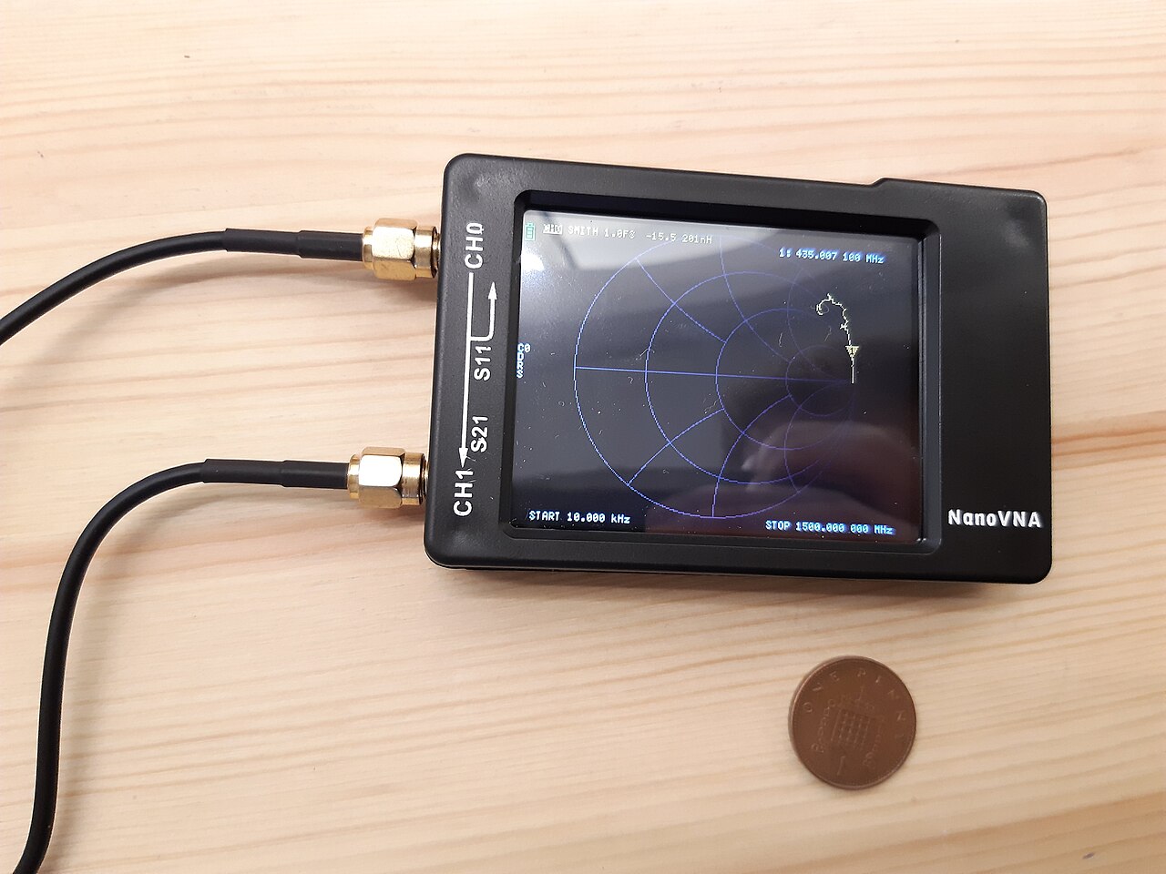
The tool that ended the guesswork
For most of amateur radio's history, measuring an antenna meant transmitting into it and watching an SWR meter at one frequency at a time. Trimming a dipole was an afternoon of climbing, cutting, lowering, keying up, and repeating. Then inexpensive vector network analyzers arrived, the NanoVNA family being the best known, and a measurement that used to take hours became a two-second sweep on a screen the size of a credit card.
If you own one piece of test equipment beyond a multimeter, this should be it. It will find the corroded connector you have been blaming on propagation, tell you exactly where your antenna is resonant instead of where you hoped, measure the length of a buried coax run without digging it up, and characterize a filter or a balun you built. The reason many operators own one and use it badly is that the calibration step is genuinely unforgiving, and an uncalibrated VNA produces confident nonsense.
What a VNA measures, in plain language
A vector network analyzer sends a small signal into a device and measures both the amplitude and the phase of what comes back. Amplitude alone tells you how much energy returned; adding phase tells you what kind of load produced that reflection. That is the difference between knowing your SWR is 2.5 and knowing that it is 2.5 because the antenna is too long and looks inductive at this frequency.
The two measurements you will use constantly are S11 and S21. S11 is the reflection at port one, which is what an antenna measurement is: connect the antenna, sweep, and read SWR, return loss, and impedance across the band. S21 is transmission from port one to port two, which is how you measure filters, attenuators, and the loss of a length of coax. Everything else the instrument offers is a different presentation of those two numbers.
Calibration is not optional
A VNA does not know where its own measurement plane is until you tell it. Calibration establishes that reference by measuring three known standards at the end of whatever cable you intend to use: an open circuit, a short circuit, and a fifty-ohm load. The instrument then mathematically removes the effect of its own connectors and your test cable from every subsequent reading.
Three rules save enormous frustration. First, calibrate at the end of the cable you will actually connect to the antenna, not at the instrument's port, because the cable is part of what you are removing. Second, calibrate across the frequency span you intend to sweep; a calibration performed from 1 to 900 MHz is far less accurate for a narrow 20 meter sweep than one performed from 13 to 15 MHz. Third, recalibrate whenever you change cables, adapters, or span. An uncalibrated sweep looks perfectly plausible and can be wrong by a factor of two.
Reading an SWR sweep
Set the span to cover the whole band plus a margin on each side and look at the shape, not just the minimum. A resonant antenna produces a clear dip. Where that dip sits tells you whether the antenna is too long, in which case resonance is below your target frequency, or too short, in which case it is above. How deep the dip goes tells you how close the feedpoint impedance is to fifty ohms at resonance. How wide the dip is tells you the bandwidth, which is a direct indicator of efficiency: a very narrow dip on a physically small antenna almost always means a lossy antenna.
The practical trimming rule follows immediately. If resonance is one percent below your target, the antenna is roughly one percent too long. Use the HAMSTATION antenna length calculator for the starting dimensions, cut deliberately long, then measure and trim in small increments, sweeping after each cut. Two or three iterations will land you within a few kilohertz, and you will never guess at a length again.
Finding faults with the time-domain view
Most NanoVNA software includes a time-domain reflectometry display, which converts a frequency sweep into a picture of what is happening along the length of the cable. A fault reflects energy, and the delay before that reflection arrives tells you how far away it is. A sharp spike partway along a run means a damaged section, a water-filled connector, or a crushed cable, and the display will tell you it is thirty-one feet out rather than leaving you to inspect a hundred feet by hand.
This one feature justifies the instrument's cost the first time you use it in anger. A feedline that has worked for five years and suddenly shows high SWR on every band has a physical fault, and TDR finds it in a minute. Without it, the standard method is to disconnect sections and test each one, which involves a ladder.
Measuring coax length and velocity factor
You can measure the electrical length of a coax run by leaving the far end open and finding the frequencies at which it looks like a short or an open. Those resonances are spaced by the cable's electrical quarter-wavelengths, and from them you can compute the physical length if you know the velocity factor, or compute the velocity factor if you know the length. This is how you cut accurate quarter-wave matching sections and phasing lines for stacked antennas, which is impossible to do reliably with a tape measure because the printed velocity factor on the jacket is nominal.
The same measurement identifies mystery cable. A reel of unmarked coax can be characterized in five minutes: measure its impedance with a known load, measure its loss with S21, and measure its velocity factor from the resonances. Then you know whether it belongs in your station or in the recycling.
Mistakes that produce nonsense
Never connect a VNA to an antenna that another transmitter is feeding, and never leave it connected when you key up. The input stage handles milliwatts, and a hundred watts will destroy it instantly. Disconnect the radio, connect the VNA, measure, and reverse the process. A cheap coax switch reduces the chance of an expensive mistake.
Be equally careful with strong ambient fields. Measuring an antenna within a few feet of a broadcast tower, or on a shared tower with an active transmitter, produces readings polluted by the signal arriving from outside. If a sweep looks erratic and irreproducible, that is often the cause. Finally, check your adapters. A worn or loose adapter is the most common source of measurements that change every time you touch the setup.
What to measure the first weekend
Sweep every antenna you own and save the traces with dates in the filenames. Those baseline sweeps are the reference you will compare against for years, and the moment something changes you will be able to prove it in thirty seconds rather than debating it.
Then measure the loss of each coax run, the response of any filters or duplexers in the station, and the common-mode impedance of your chokes if the software supports it. By Sunday evening you will have a documented station and you will almost certainly have found one thing that was quietly wrong. Everyone does.
Every HAMSTATION tool runs entirely client-side. No accounts, no tracking, no server storage.
Open the toolkit →